

1 引言
出来,如反馈线性化、反步控制法、滑模控制、无源控制以及自抗扰控制等。基于反馈线性化控制理论的控制器设计方法需要全状态可测量、需要精确抵消动态、会引入控制器奇异性,对参数的依赖性较大、控制律复杂。反步控制法计算量大,实时性差[4];滑模控制会给系统带来抖动问题[2]。1989年由Ortega 等[5]提出的无源控制(Passivity based control,PBC)由于其能量耗散特性可实现系统的全局稳定性,无奇异点等优点,现已应用到机械、电气、机电等各个控制领域[6]。文献[1-2,7]利用无源控制分别对Buck变换器、Buck-Boost变换器进行控制,均实现了系统的稳定运行,并且拥有良好的动态和稳态性能。但是PBC依赖精确的数学模型,在系统受扰动或者内部参数发生变化时,会存在静态误差问题。
因此,针对上述问题,以Buck变换器为例,建立基于欧拉拉格朗日(Euler Lagrange,EL)模型的无源控制器。首先保证系统的稳定性,对于无源控制在系统受扰动或者参数变化时存在的静态误差问题,文献[2,7-9]都采用PI控制结合PBC,但是该控制方法存在快速性与超调之间无法调和的矛盾,因此本文结合ADRC可以把系统的未建模动态和未知扰动作用都归结为对系统的“总扰动”而进行观测并予以补偿的优点,从而解决PBC存在的问题,使系统具有更加良好的鲁棒性。
最后利用Matlab/Simulink中搭建的仿真模型,进行了仿真研究,并与PI+PBC、PI控制方法进行比较,试验结果验证了本文所提控制策略的正确性以及有效性。
2 Buck变换器无源控制
2.1 Buck变换器数学模型
Buck变换器的拓扑结构如图1所示,其中V为IGBT,VD为二极管,L为电感器,C为电容器,R为电阻,E为电源电压,${{i}_{L}}$为通过电感器的电流,${{u}_{o}}$为电容器两端的电压。
图1
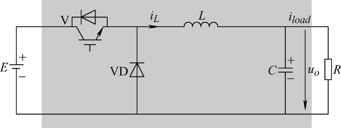
假设电路中的元器件均为理想元器件,在连续导通模式(Continuous conduction mode,CCM)下工作,选择电感电流开关周期平均值${{i}_{L}}$和电容电压开关周期平均值${{u}_{o}}$为状态变量,即$x={{[\begin{matrix} {{x}_{1}} & {{x}_{2}} \\\end{matrix}]}^{\text{T}}}={{[\begin{matrix} {{i}_{L}} & {{u}_{o}} \\ \end{matrix}]}^{\text{T}}}$。
由图1可得,Buck变换器的数学模型为
式中,d为Buck变换器V的占空比,$0\le d\le 1$。
于是,由式(1)可得Buck变换器的EL模型为
式中,$\mathbf{M}=\left( \begin{matrix} L & 0 \\ 0 & C \\\end{matrix} \right)$;$\mathbf{J}=-{{\mathbf{J}}^{\text{T}}}=\left( \begin{matrix} 0 & 1 \\ -1 & 0 \\ \end{matrix} \right)$为反对称矩阵;$\mathbf{R}=\left( \begin{matrix} 0 & 0 \\ 0 & {\scriptstyle{}^{1}/{}_{R}} \\ \end{matrix} \right)>0$;$\mathbf{u}=\left( \begin{matrix} dE \\ 0 \\ \end{matrix} \right)$;$\mathbf{y}$为输出变量。
下面分析Buck变换器的无源性。
设系统能量存储函数为
可得
从式(4)可以证明,该系统是严格无源的,因此,Buck变换器必然稳定[4]。
2.2 无源控制器设计
设期望的状态变量为${{\mathbf{x}}^{\mathbf{*}}}={{[\begin{matrix} x_{1}^{*} & x_{2}^{*} \\\end{matrix}]}^{\text{T}}}=$${{[\begin{matrix} i_{L}^{*} & u_{o}^{*} \\ \end{matrix}]}^{\text{T}}}$,状态变量误差为${{\mathbf{x}}_{e}}=\mathbf{x}-{{\mathbf{x}}^{\mathbf{*}}}$。无源控制器的作用是加速系统误差能量收敛到0,误差能量存储函数为
可得
为加速误差能量存储函数快速收敛到0,需要进行阻尼注入。可得
式中,${{\mathbf{R}}_{a}}=\left( \begin{matrix} {{R}_{a1}} & 0 \\ 0 & {\scriptstyle{}^{1}/{}_{{{R}_{a2}}}} \\ \end{matrix} \right)>0$为注入阻尼矩阵。 令式(7)等于0,可得无源控制器为
于是
由式(9)可知,误差能量存储函数可以收敛到0,式 (8)所得的无源控制器可实现控制目的。
于是,根据无源控制器(式(8))可得Buck变换器的占空比为
3 自抗扰控制器设计
图2
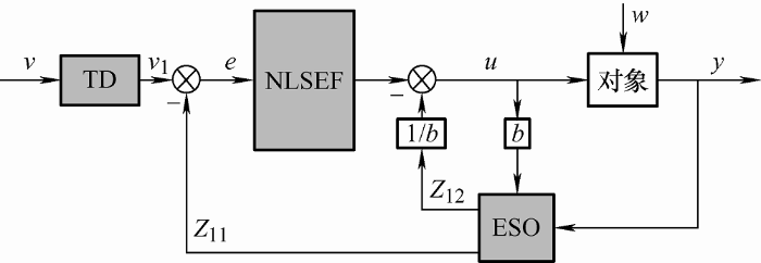
Buck变换器输入侧与输出侧的功率平衡表达式为
将式(11)整理成为自抗扰控制器的规范形式为
式中,$b=\frac{E}{C{{u}_{o}}}$;$u=i_{L}^{*}$;$w=\frac{1}{C}{{i}_{load}}$。
由于为一阶系统,并且对流向负载的电流${{i}_{load}}$进行直接测量,因此,简化后的自抗扰控制框图如图3所示。
图3
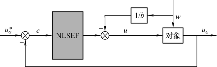
为了解决PI控制存在的问题,ADRC采用非线性组合,引入fal函数。于是,误差反馈控制律为
式中,$e=x_{2}^{*}-{{x}_{2}}$;$\beta $为可调参数;$\alpha $为0~1的常数;$\delta $为影响滤波效果的常数。
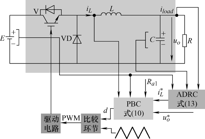
将通过自抗扰技术求得的电感电流期望值$i_{L}^{*}$代入无源控制律中,便可得到基于自抗扰控制的Buck变换器无源控制律,其控制框图如图4所示。
图4
4 仿真研究
表1 系统仿真参数
| 参数 | 数值 |
|---|---|
| 电源电压E/V | 400 |
| 电感器电感L/mH | 2 |
| 电容器电容C/μF | 1 100 |
| 负载电压期望值$u_{o}^{*}$/V | 300 |
| 电阻阻值R/Ω | 100 |
| 变换器开关频率fs/kHz | 10 |
本文采用方法②来选取注入阻尼Ra1的数值。通过调试,最终选取Ra1 = 30 Ω。
图5
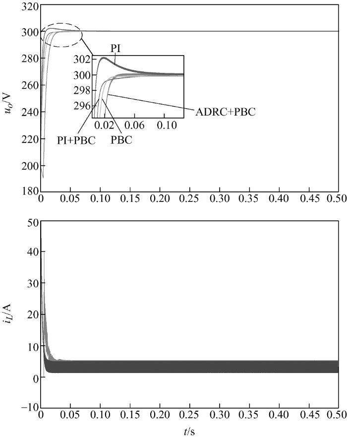
为了验证该控制策略的鲁棒性,在0.5 s以及1 s时投切50 Ω电阻负载,从图6中可以看出PBC在Buck变换器投切负载的过程中,负载电压会偏离期望电压值,而PI控制、PI+PBC控制以及ADRC+PBC控制可以克服此问题,恢复到期望电压值,其中ADRC+ PBC控制中负载电压变化幅度最小,恢复时间最短。
图6
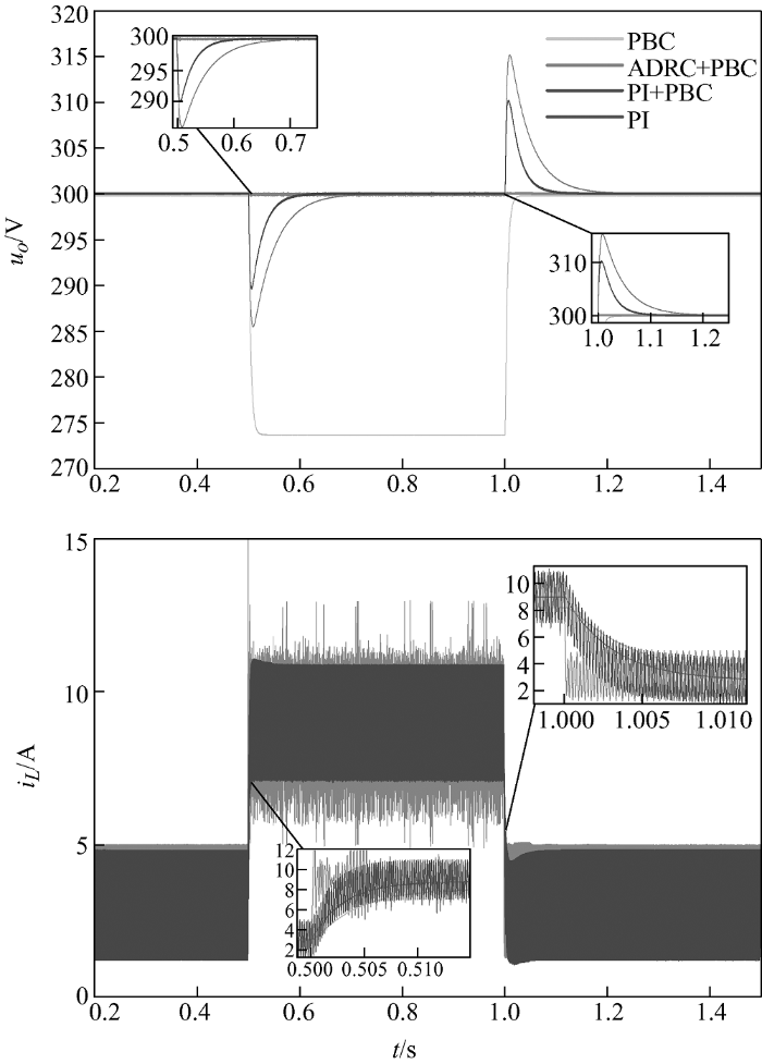
图7
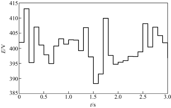
图8
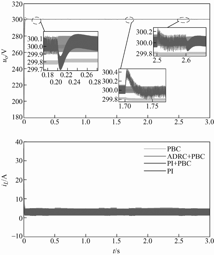
从上述仿真结果便可以看出,本文所提控制策略可以解决PBC控制在系统受扰动时存在的静态误差,同时与PI+PBC、PI控制方法相比,负载电压变化幅度较小,恢复时间更快,具有良好的鲁棒性,从而验证了本文所提控制策略的有效性以及优越性。
5 结论
本文针对无源控制(PBC)在受系统扰动时存在静态误差问题,结合自抗扰控制(ADRC),即内环PBC,外环ADRC,较好地解决了此问题。与其他控制方法相比较,本文所提控制策略具有以下优势。
(1) 无源控制由于其能量耗散特性,可实现系统的全局稳定性。
(2) 结合自抗扰控制后,在系统受扰动的情况下,负载电压变化较小,恢复时间更快。
该控制策略可推广到其他类型变换器。
参考文献
Adaptive passivity-based control of DC-DC buck power converter with constant power load in DC microgrid systems
[J].
基于最优阻尼注入的Buck变换器无源控制研究
[J].
Study of passivity-based control of buck converter based on optimal damping injection
[J].
Passivity-based control of DC microgrid for self-disciplined stabilization
[J].
Adaptive motion control of rigid robots:A tutorial
[J].DOI:10.1016/0005-1098(89)90054-X URL [本文引用: 1]
Intercon- nection and damping assignment passivity-based control of port-controlled Hamiltonian systems
[J].
DOI:10.1016/S0005-1098(01)00278-3
URL
[本文引用: 1]

Abstract
Passivity-based control (PBC) is a well-established technique that has shown to be very powerful to design robust controllers for physical systems described by Euler–Lagrange (EL) equations of motion. For regulation problems of mechanical systems, which can be stabilized “shaping” only the potential energy, PBC preserves the EL structure and furthermore assigns a closed-loop energy function equal to the difference between the energy of the system and the energy supplied by the controller. Thus, we say that stabilization is achieved via energy balancing. Unfortunately, these nice properties of EL–PBC are lost when used in other applications which require shaping of the total energy, for instance, in electrical or electromechanical systems, or even some underactuated mechanical devices. Our main objective in this paper is to develop a new PBC theory which extends to a broader class of systems the aforementioned energy-balancing stabilization mechanism and the structure invariance. Towards this end, we depart from the EL description of the systems and consider instead port-controlled Hamiltonian models, which result from the network modelling of energy-conserving lumped-parameter physical systems with independent storage elements, and strictly contain the class of EL models.
带恒功率负载的Buck-Boost变换器稳定性研究
[J].
Study on the stability of Buck-Boost converter with constant power load
[J].
An interconnection and damping assignment passivity-based controller for a DC-DC boost converter with a constant power load
[J].
DOI:10.1109/TIA.2013.2290872
URL
[本文引用: 1]
This paper proposes an adaptive interconnection and damping assignment (IDA) passivity-based controller (PBC) with a complementary proportional integral (PI) controller for dc-dc boost converters with constant power loads (CPLs). The plant is modeled as a port-controlled Hamiltonian system (PCHS). A virtual circuit that interprets the parameters of the PCHS is then derived to determine the parameters of the IDA-PBC for the system to work in the underdamping, critical-damping, and overdamping modes. Moreover, a complementary PI controller is designed to eliminate the steady-state output voltage error of the IDA-PBC caused by the load variation. Simulation studies are carried out inMATLAB/Simulink to validate the proposed control algorithm for a dc-dc boost converter with a CPL; results show that the proposed control algorithm ensures the stability and fast response of the system in different modes when the load changes. Experimental results are provided to further validate the design and simulation of the proposed control algorithm.
基于端口受控哈密顿系统模型的带恒功率负载的Buck变换器控制
[J].Port-controlled Hamiltonian systems and passivity-based control theory was applied to a Buck converter with constant power load. A Hamiltonian modeling of the buck converter was established and then analyzed for the stability of the equilibrium. The feedback controller was also designed. The simulation results show that control system has a good dynamic and steady state performance through adjusting controller parameters.
Buck converter control with constant power load based on port-controlled Hamiltonian system model
[J].Port-controlled Hamiltonian systems and passivity-based control theory was applied to a Buck converter with constant power load. A Hamiltonian modeling of the buck converter was established and then analyzed for the stability of the equilibrium. The feedback controller was also designed. The simulation results show that control system has a good dynamic and steady state performance through adjusting controller parameters.


